
Pre-order
Tröndle Embedded Systems
Free shipping over €75 in NL · €150 in the EU & UK
Question about this part? Ask me
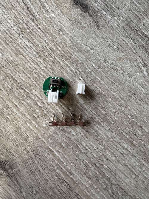
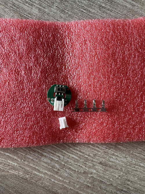
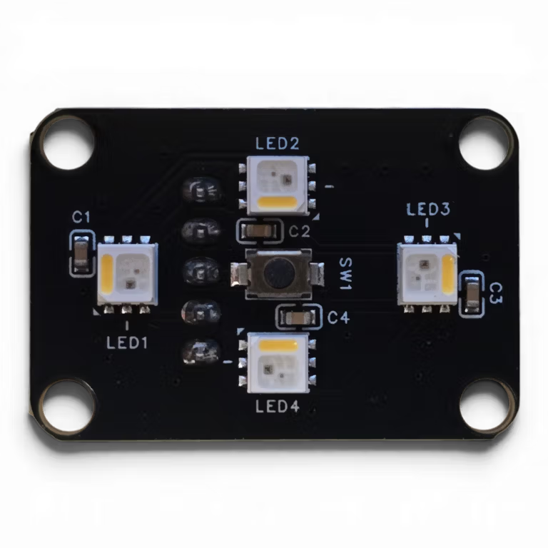
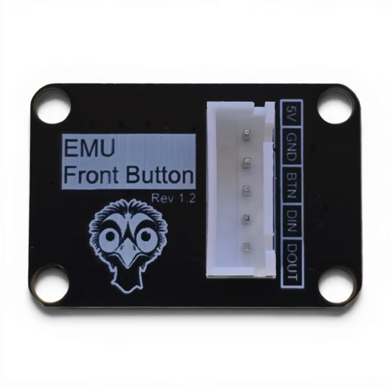
This PCB goes behind the eject button on each EMU lane. Four RGBW LEDs light the button up, so Happy Hare can show load and unload animations, and an SMD switch gives a crisper click than the D2F switch with magnets. It also cuts down the wiring and soldering in the button.
chain_count: 5 per lane: LEDs 1–4 are the button (exit LEDs), LED 5 is the dry box (entry LED).! (^!mmu0:EJECT_BUTTON), unlike the D2F setup.In stock in the Netherlands, ships in 1–2 working days with no import fees.
For the EMU by DW-Tas and igiannakas. Sourced from the EMU project's licensed PCB maker. Assembly: EMU LED Button PCB manual
Printed to order and shipped tracked from the Netherlands, usually within 2–4 working days. Free over €75 in NL and €150 in the EU & UK.
PLA, PETG or ABS depending on the part. Wipe clean, and keep it out of a hot car.
Changed your mind? You can return or exchange within 14 days of arrival — just email me and I'll sort it out. Please send it back complete and, where possible, in its original packaging.
You might also like